

SHIP MANEUVERING ASSISTANCE SYSTEMS
Gemi manevrası yardımcı sistemleri dendiğinde ilk akla gelen güncel teknoloji “Dynamic Positioning System - Dynamic Positioning System (DPS)” Olarak adlandırılan sistemdir.
Although this system is not the main subject of this article, to summarize briefly:
Today, it is a maneuvering system that performs maneuvers with extreme precision for marine vessels that require very high positional accuracy, such as platform support vessels and specialized tugboats handling anchoring.
“Dinamik Konumlandırma Sistemi” bunu gerçekleştirirken hatası sadece santimetrelerle ifade edilen DGPS pozisyon verilerine ek olarak platform üzerine sabitlenmiş beacon'larla radar ve sonar sinyallerinden de faydalanır. Sistem istenen manevrayı “Kalman Filter” denilen bir yöntemi kullanarak minimum sapma ile yerine getirir. Aslında bu filtreleme yöntemi bir anlamda otopilotların çalışma prensibinin çok daha karmaşık ve hassas bir biçimidir diyebiliriz.
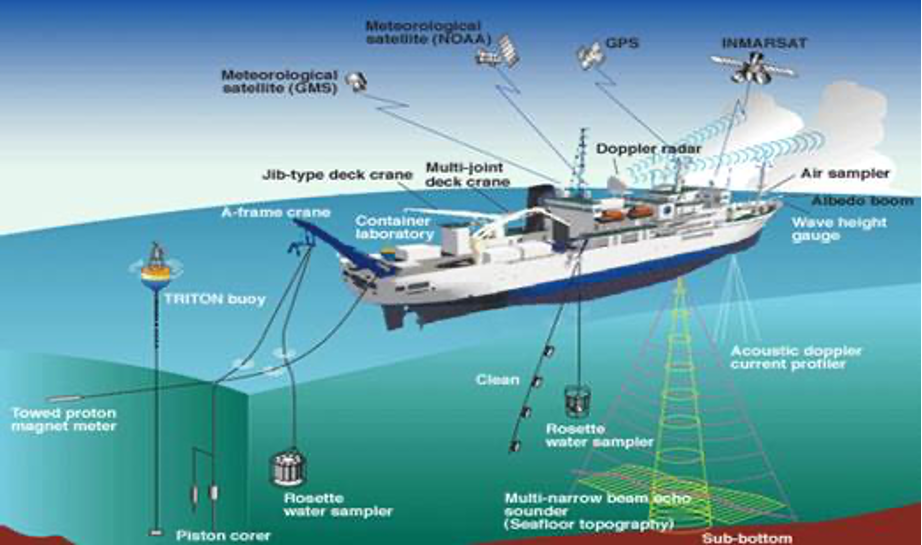
Figure-1 Main system parameters of the DPS
The “Dynamic Positioning System” performs its function with a precision expressed in centimeters, and frankly, it is not possible to execute the mentioned maneuvers with the same precision and minimal deviation values using human perceptions.
“Dynamic Positioning System Operators” özel kurslarla yetiştirilir ve are certified.
Currently, the "Dynamic Positioning System," which is a relatively expensive technology, has only found widespread use in the specialized vessels mentioned above. However, with the advancements in artificial intelligence in this field, the technology has started to become relatively cheaper and has begun to be used in some passenger ships as well.
Although the "Dynamic Positioning System" continues to be a relatively expensive technology, it is crucial to recognize that the performance of computer and artificial intelligence-supported applications in ship maneuvering, such as DKS, has already surpassed the accuracy and precision of human perceptions.
“Dinamik Konumlandırma Sistemi”nin çok kısa bir özetini yaptıktan sonra uzunca bir süredir özellikle tanker ve gaz terminallerinde yaygın kullanım alanı bulan ve gemi manevrasının emniyetine oldukça yardımcı diğer bir araçtan “Docking Aid Indicator” olarak tanımlayabileceğimiz (Docking Aid Systems - DAS) sistemini ele alacağız
The main parameters of the docking aid indicator system are shown in Figure 2.
consisting of the following headings:
1. Laser Sensors
2. Dashboard
3. Main Computer
4. Processor
5. Handheld Unit
6. Maneuvering Screen
7. Auxiliary Sensors
a. Current Sensor
b. Tidal Sensor
c. Weather Sensor
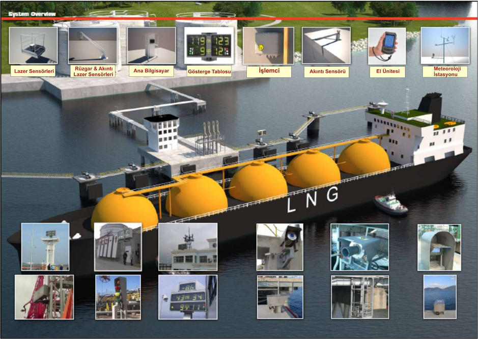
Figure-2 Berthing auxiliary indicator basic parameters
If we take a look at these parameters in order:
1. Laser Sensors: Lazer sensörleri yanaşmanın yapılacağı rıhtıma en az 25 metre arayla yerleştirilirler.
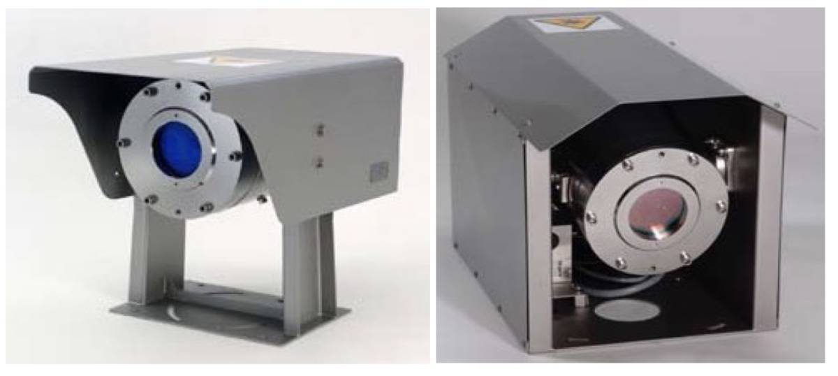
Şekil-3 Laser Sensors
The number and spacing of laser sensors are arranged in such a way that they will definitely control the bow and stern points of the vessel to be berthed, taking into account various ship sizes that will approach the dock.
düzenlenir.
Laser sensors enable the calculation of the bow-stern distance and bow-stern approach speed of the vessel generally from 300 meters away, using non-harmful Class 1 infrared energy beams they emit.
Laser sensors are generally made of stainless steel or aluminum bodies and are placed on a telescopic base that can extend and retract. This prevents them from coming into contact with water depending on the tidal conditions.
Laser sensors take the contact surface of the fenders as the zero point.
2. Display Panel: Display panels are large panels that allow the ship's captain and pilot to see the calculated bow-stern distance and bow-stern approach speeds, which are determined by the beams emitted by the laser sensors, from approximately 250 meters away, both day and night.
They are typically mounted on bases that vary between 1 to 4 meters in height. The display panel can generally rotate +/- 35 degrees both vertically and horizontally, thus accommodating variable bridge heights and ship length variations.
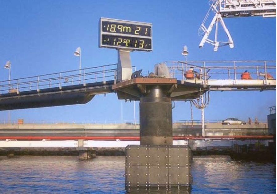
Figure-4 Berthing Assistance System Display Panel
Figure-4 Berthing Assistance System Display Panel
As seen in Figure-4, the upper part of the panel displays the bow and stern distances side by side in 3 digits (0.0-19.9 m, 20-200 m).
Below the panel, the bow and stern approach speeds are given in 2 digits as cm/s (0-99 cm/s).
Additionally, there are three colored warning lights on the panel: red, yellow, and green.
The red light indicates that the maximum speed parameter for a specific distance is being exceeded very quickly.
When the yellow light is on, the vessel is approaching the dock at a speed above the designated ideal speed parameter from the bow or stern, or from both.
If the green light is on, the vessel is approaching the dock at a speed safely below the designated speed parameter.
Generally, when there is a distance of 100-150 meters to the dock, an approach speed of 24 cm/s is considered normal, while in the final stages of berthing, this parameter is adjusted to below 10 cm/s.
Genellikle rıhtıma bordasal olarak 100-150 metre mesafe kaldığında 24 cm/sn bir bordasal yaklaşma hızı normal kabul edilirken, yanaşmanın son aşamasında bu parametre 10 cm/sn değerinin altına ayarlanır.
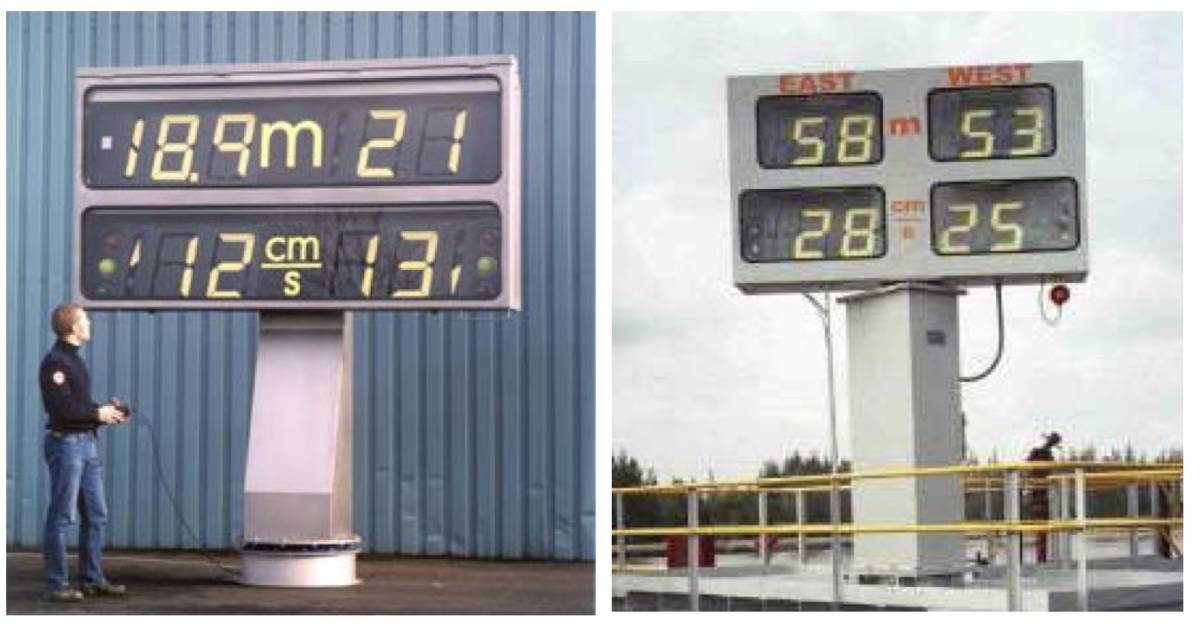
Figure-5 Two similar indicator panels
3-4. Main Computer ve Processor Ünitesi: Data from laser sensors and other auxiliary sensors (current, tide, wind sensors) pass through the processor unit on the main computer to provide us with speed and distance values.
Other computers of the terminal can be connected in parallel to the main computer. The processors in question have been designed by manufacturers to be completely independent and unaffected by power outages.
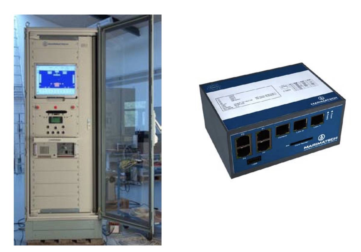
Figure-6 Main computer and processor
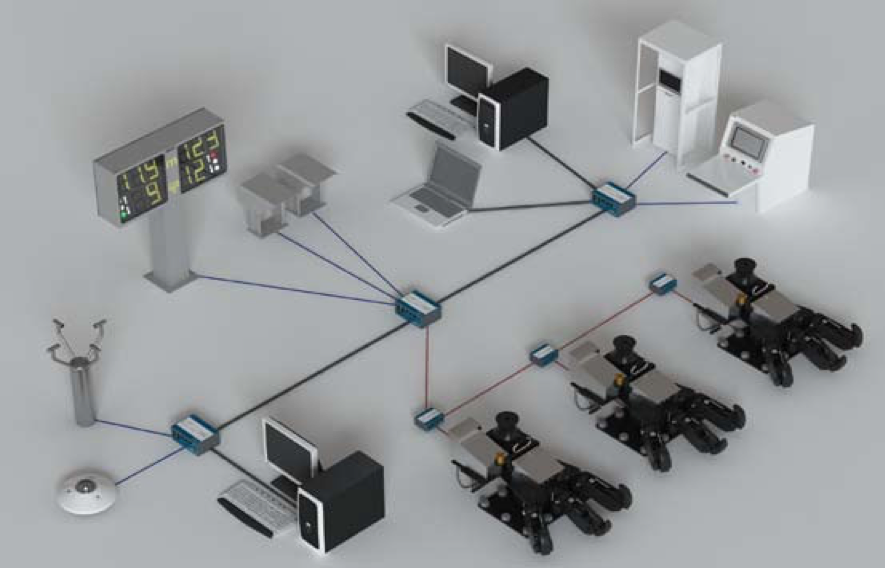
Figure-7 System operation diagram
5. Handheld Unit (Portable Pilot Unit – PPU): Pager olarak niteleyebileceğimiz taşınabilir el üniteleri gösterge panelinde yer alan bilgileri gemi kullanıcısının üzerinde taşıyabileceği kadar küçük bir cihaz üzerinde görülebilmesini sağlar. Anten ve frekans gücüne göre bu cihazlar bilgileri yaklaşık 2-3 km mesafeden almaya başlayabilir. Bilgiler UHF frekansından gönderilir (464-468 MHz).
Distance and speed information is transmitted on the LCD, illuminated if desired, across four lines, each capable of being 20 characters long, as shown in Figure-8.
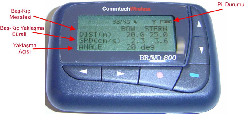
Figure-8 Portable pilot unit
The angle value seen in the bottom row of the figure indicates the angle at which the ship is approaching the dock line. If this angle is positive, the bow of the ship is closer to the dock than the stern (Bow-in). If the angle value is negative, the stern of the ship is closer to the dock than the bow.
6. Auxiliary Sensors: Sistemin yardımcı unsurlarından biri olan akıntı sensörü Doppler prensibi ile çalışır ve suya gönderdiği akustik sinyaller sayesinde akıntı hızı, yönü ve su sıcaklığı ölçülür.
The tidal parameter is detected through laser sensors under all conditions of snow, rain, and sea state.
The air station in the system is equipped with sensors that measure wind speed and direction, precipitation, barometric pressure, temperature, and relative humidity. All this information is instantly transmitted to the main computer within the system and can be viewed on the screen.
7. Maneuvering Screen: Minor differences in screen presentation according to various manufacturers
The maneuver can be monitored at every stage from the terminal and all connected computers in a bird's-eye view or as a graphical representation of the bow-stern distance and speeds. All this information is recorded and stored in the system's memory.
On the screen, all information such as bow-stern distance, bow-stern approach speed, the ship's lateral transfer track, the points where the ship should stop and start lateral transfer, wind speed and direction, current speed and direction, etc., can be displayed as desired. When we glance at the maneuver screen shown in Figure-9, in addition to all the mentioned information, the positions of the laser sensors are also displayed on the screen. The directions and forces of wind and current are shown on the left side of the screen. However, a notable difference here is that while the angle value is generally expressed as positive when the bow of the ship is close, it is shown as negative in this example. The section where the stern of the ship will dock is indicated as North, while the section where the bow will dock is indicated as South.
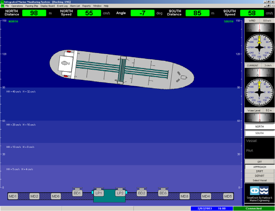
Figure-9 Bird's-eye maneuver screen
The ship is approaching the dock at a speed of 58 cm/s, which is higher than that of the stern.
In Figure-10 There is a screen that displays a graphical representation instead of the actual image.
When the graph is examined, it is initially observed that the bow of the ship is approaching the dock more closely, but at 08:45, the distance from the bow is 31 meters and from the stern is 39 meters, at which point the ship's approach has stopped and it has begun to move away from the dock.
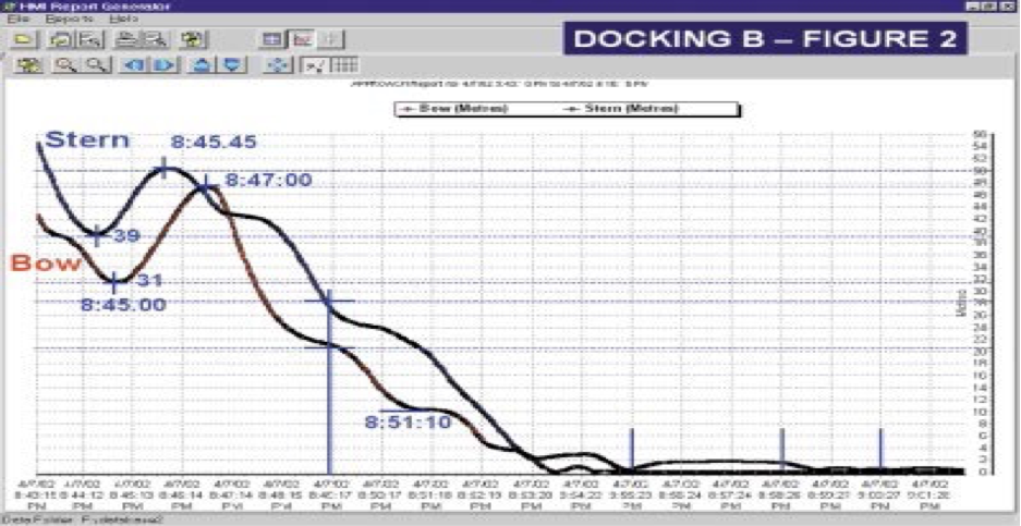
Figure-10 Graphical maneuver screen
This is clearly visible from the U profile on this graph. Shortly after 08:47, the stern of the ship was closer to the dock than the bow for a while, but soon the situation reverted to its previous state. Additionally, after 08:47, the ship has noticeably begun to approach the dock again.
Conclusion: Docking assistance systems make an extremely positive contribution by eliminating the risk of human perception errors and inadequacies by conveying critical information to ship users at every moment of the docking maneuver.
Within the framework of "Docking Assistance Systems" discussed in this article, particularly the "Dynamic Positioning System," human perception acts almost as a secondary element alongside technology.
With artificial intelligence rapidly making its impact felt in every area of life, we can foresee that these developments will significantly enhance and change the conventional ship maneuvering advisory and format in the not-so-distant future.
Sincerely,
Capt. Alpertunga Anıker
Source: www.denizhaber.com